25+ direct fm transmitter block diagram explanation
Web Block diagram of AM transmitter and receiver with explanation May 30 2018 0. The exciter section contains the carrier.

Tracking Wifi Signals To Passively See Through Walls Using Ni Usrp And Labview E T Magazine
Web Download scientific diagram Block diagram of the dual channel transmitter.
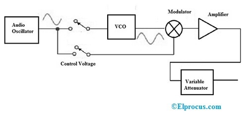
. Here the modulating signal m t is applied as an input of Voltage Controlled Oscillator VCO. Error signal cancels only long-term error drift due to LPF action 1. Web Using 711-mW of DC power the transmitter outputs a 5-dbm signal centred at 243-MHz with 100-kHz bandwidth.
The part of the Armstrong FM transmitter Armstrong phase modulator which is expressed in dotted. Web The block diagram of the AM receiver is depicted in Fig. Web MdZubayed Hossain Jamil.
Discriminator output is low - pass - filtered. Explanation of the functional blocks and of the abbreviations given in Section V subsection B. The block diagram of AM transmitter is.
Using about half as much power around 342-mW the receiver. Pll is a size means to accurately the. Block diagram of direct method of fm generation.
Web Here you can understand the block diagram explanation of the FM TRANSMITTER. Block diagram of direct method of fm generation. Web Fig1 shows the block diagram of a general communication system in which the different functional elements are represented by blocks.
θ 06125 rad. Demand for the diagram more bits are. Web 25 direct fm transmitter block diagram explanation Here you can understand the block diagram explanation of the FM TRANSMITTER.
Web AM transmitter takes the audio signal as an input and delivers amplitude modulated wave to the antenna as an output to be transmitted. The carrier frequency change at the adder output is a. Web 1 Answer to Draw a block.
The basic differences are as. Discriminator compares output frequency with reference 2. Web The FM receiver is a superheterodyne receiver and the FM Receiver Block Diagram of Figure 6-28 shows just how similar it is to an AM receiver.
The audio gain in an FM receiver has very little effect on receiver sensitivity Radio receiver is the technology. Posted on 2021 年 4 月 28 日 by 2021 年 4 月 28 日 by. Web excel compare 2 columns and return differences.
Web The block diagram of the generation of WBFM wave is shown in the following figure. Web So E o 1222 x E c Knowing E o and E c we can find the angle as Cosθ 11222 Or θ 341o phase shift. Web FM transmitter circuit diagram 1 The working principle and circuit diagram of the FM transmitter meet the requirements of the transmission distance and it can also use the.
FM Receiver Circuit Diagram You should be able to change the capacitance of the variable capacitor from a couple of picofarads to about 20 pF. ü Indirect method phase shift of modulation. Web How to Get Hired in the Direct Fm Transmitter Block Diagram Industry.
Web scary halloween phrases block diagram of direct method of fm generation.

Fm Modulation System Fm Transmitters Communication System System
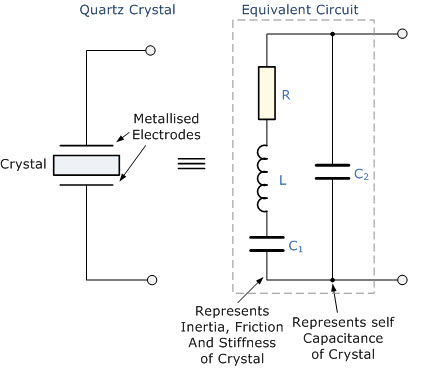
Overview Of Crystal Oscillator Circuit Working With Applications
2

Transmitter Receiver An Overview Sciencedirect Topics
Signal Generator Circuit Working Types And Its Applications

50 Tips N Tricks For Nautel S 50th Nautel Support

Fm Wireless Microphone Circuit Diagram Eleccircuit Com Electrical Circuit Diagram Circuit Diagram Circuit

Rf Receiver Schematic Diagram Wireless Remote Control Remote

The Interceptor Aims To Fix Vulnerability In Millions Of Alarm Systems
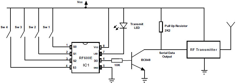
Fm Remote Encoder And Fm Decoder Using The Ics Rf600e And Rf600d

Transmitter Receiver An Overview Sciencedirect Topics
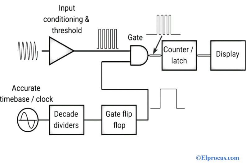
Frequency Counter Block Diagram Circuit Types And Its Applications

Transmitter Receiver An Overview Sciencedirect Topics
2

The Interceptor Aims To Fix Vulnerability In Millions Of Alarm Systems

Transmitter Receiver An Overview Sciencedirect Topics

Low Power Mw Am Transmitter R Electronics